
In the molded fiber packaging industry, the precision of your molds directly dictates your final product’s yield rate and production efficiency. When packaging manufacturers seek a pulp molding mold manufacturer for custom molded pulp tooling, communication gaps often lead to excessive design revisions, failed trials, or tools that cannot be mounted on existing production lines.
To ensure your custom molds are designed right the first time, procurement managers and tooling engineers must prepare four core categories of information before contacting a supplier: product design specs, equipment interfaces, pulp characteristics, and procurement acceptance criteria. Below is the complete preparation checklist from Hanson Pulp Molding.
1. Product Design and Physical References
Product design files form the foundation of molded fiber tooling. They determine cavity layout, draft angles, and demolding mechanics.
3D CAD Models and 2D Drawings
-
3D File Formats: Provide 3D models preferably in STEP (.stp) or IGES (.igs) formats. This allows mold designers to evaluate whether the draft angles, undercuts, and radii (R-corners) comply with pulp molding constraints.
-
2D Engineering Drawings: PDF or CAD formats detailing critical dimensions, strict tolerances (especially for assembly features), estimated product weight, and required wall thickness.
Physical Samples and Packaged Goods
-
Existing Samples: For reverse engineering or upgrading an existing molded fiber product, sending a physical sample is highly effective.
-
The Packaged Item (For Custom Inserts): If you are developing industrial protective packaging inserts, providing the actual item to be packaged—or its precise 3D boundary model—helps designers map out optimal cushioning gaps and structural support points.
2. Equipment Interfaces and Machine Specifications
A well-designed mold must seamlessly integrate with your existing machinery. If you are using non-Hanson molding machines, the following parameters are mandatory for accurate tooling customization:
-
Platen Dimensions and Mounting Layout: The exact size of the upper and lower platens of your forming and hot-press machines, the effective forming area, and a detailed map of the mounting/locking holes (preferably OEM machine drawings).
-
Heating System and Temperature Control: For hot-press molds, specify the heating method (electric cartridge heaters, thermal oil, or steam). For electric setups, specify heater diameter, power output, and wiring layouts; for thermal oil, provide the fluid port specifications.
-
Air/Vacuum/Water Ports: Specify the vacuum suction port dimensions, compressed air blow-off locations, and pipe diameters for forming molds to ensure pneumatic and hydraulic systems connect perfectly.
-
Shut Height and Stroke: The machine’s minimum/maximum shut height and mold-opening stroke limits. This prevents scenarios where a newly manufactured mold is too tall to close or lacks sufficient clearance to eject the product.
3. Pulp Material Properties and Shrinkage
Molded fiber tooling operates differently from plastic injection molding. Pulp products undergo significant shrinkage during drying and hot pressing. Material properties directly dictate the shrinkage compensation factor applied during tool design.
-
Pulp Furnish (Material Composition): Specify whether you are using bagasse (sugarcane), wood pulp, bamboo pulp, or recycled corrugated containers (OCC). Shrinkage rates vary wildly based on fiber length (typically ranging from 3% to 8%).
-
Process Route: Clarify if this is for a dry-press process (natural/oven drying, requiring forming and transfer molds) or a wet-press process (in-mold thermoforming, heavily reliant on hot-press tools and mesh configurations).
-
Chemical Additives: Mention if you use heavy sizing agents or oil/water repellents, as this might influence the choice of surface treatments on the mold (e.g., Teflon non-stick coatings).
4. Production Targets and Acceptance Criteria
Before mold manufacturing begins, both parties must establish baseline targets for what constitutes a successful tool. This is vital for your procurement acceptance phase.
-
Capacity and Cavitation: Desired number of cavities (e.g., 4-out, 8-out) and target cycle times for forming and pressing.
-
Quality Tolerances: Agreed-upon maximum weight variance, thickness limits, and visual defect thresholds (e.g., flash limits, mesh mark visibility, and surface smoothness).
-
Trial Expectations: Determine if the mold manufacturer will conduct a sample run on their in-house equipment and ship prototypes, or if on-site support is required for commissioning at your facility.
How Hanson Pulp Molding Supports Your Tooling Needs
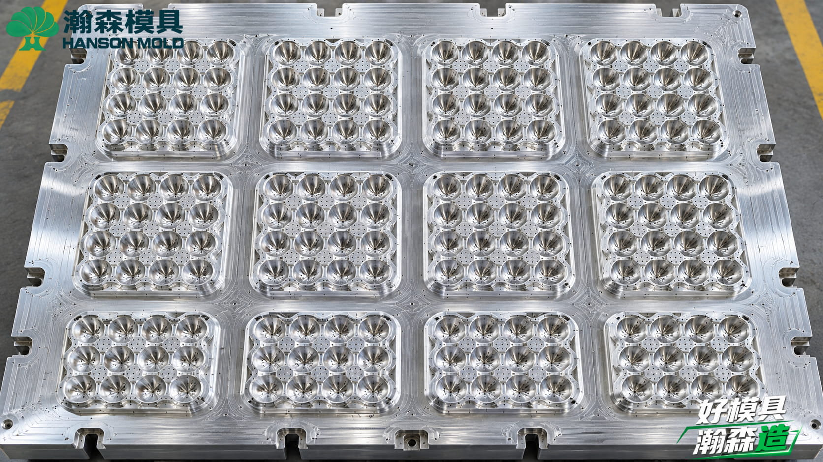
With a dedicated tooling division, Hanson Pulp Molding has manufactured over 500 pulp molding molds to date. We understand the complex synergy between tooling, pulp variations, and machine dynamics.
Backed by 10 senior designers and high-speed CNC machining centers (reaching up to 24,000 RPM spindle speeds), we utilize 3D scanning for stringent quality control. From rough machining and stress relief to precision milling, mesh covering, and final assembly, every node is controlled. Whether you are developing new molds for Hanson equipment or optimizing existing tools for non-Hanson machines, we offer complete mold services spanning from design and prototyping to mass production support.
-
FAQs:
-
Can you manufacture a mold if I only have a physical sample and no 3D CAD file? Yes. Hanson Pulp Molding has full 3D scanning and reverse engineering capabilities. You can ship the physical sample or the item to be packaged to us. Our designers will scan the object to create a high-precision 3D model, applying the correct draft angles to generate production-ready drawings.
-
What if I don’t know the exact shrinkage rate of my custom pulp blend? If you are using a new furnish formula with no historical data, we highly recommend building a single-cavity prototype mold first. By running this test mold through your actual forming and drying process, we capture accurate shrinkage data, which is then applied to calibrate the final multi-cavity production tooling, minimizing risk.
-
Can you verify and test molds designed for non-Hanson machinery? For molds designed for third-party equipment, we conduct rigorous CMM (Coordinate Measuring Machine) dimensional checks and factory acceptance inspections before shipment. While we may not replicate your exact proprietary machine for a physical trial, we supply comprehensive QC reports and can arrange on-site engineering support during your initial production run.
-
-
Ready to develop high-yield custom molded pulp tooling? Contact Hanson Pulp Molding for a free tooling evaluation and quote based on your 3D files. [International contact to be confirmed]