
Verifying Multi-Cavity Tooling Consistency in Pulp Molding: From Spot Checks to Data-Driven Records
During the commissioning of a new multi-cavity molded fiber tool, operators frequently encounter consistency fluctuations. Products formed in the center cavities might meet all specifications, while those on the outer edges suffer from lighter weights, uneven thicknesses, or localized sticking. Relying on random spot checks by operators to evaluate tooling quality is risky; once mass production begins, the defect rate can easily spiral out of control.
To ensure uniform quality across the entire platen, the project delivery and tooling acceptance processes must shift from “blind spot checks” to “systematic data recording.” Below are the core steps to implement a rigorous consistency verification process for multi-cavity molded pulp tooling.
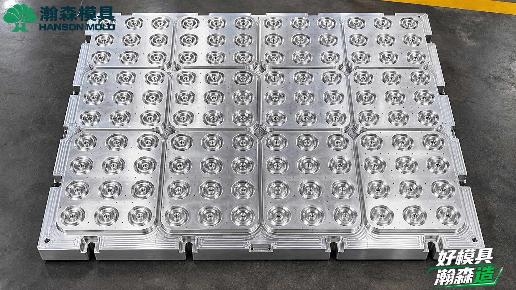
4 Practical Steps for Establishing Consistency Records
1. Single-Cavity Marking and Numbering
Traceability begins at the design and manufacturing stage. Every single cavity must have a unique identifier. We recommend engraving cavity numbers on the non-forming surfaces of the mold (such as the flange edges) and incorporating microscopic protruding dots or tiny numbers on an inconspicuous area of the molded product (like the bottom base).
-
The Goal: When a full batch of products is formed during a mold trial, quality inspectors can immediately trace any defective product back to its exact cavity location on the machine, eliminating guesswork.
2. Defining Measurement Frequency and Sampling Timing
Consistency inspection must cover different stages of the tooling trial, not just the first article:
-
Thermal Cycle Stages: Sample full platens during machine startup (cold state), after 30 minutes of continuous running (thermal equilibrium), and after 2 hours of continuous operation.
-
Sampling Matrix: Each time a sample is pulled, all products from that specific shot must be measured. Collect data from 3 to 5 consecutive shots to build a matrix. This helps determine if the deviation is random or isolated to specific cavities.
3. Setting Allowable Tolerance Thresholds
Because the pulp molding process relies heavily on the fluidity of the pulp slurry, absolute zero-variance is unattainable. Setting realistic tolerance levels is essential:
-
Weight Variance: For standard industrial packaging, a single-cavity weight tolerance of ±5% to ±8% is typical. For premium high-end packaging or tableware, it should be tightened to ±3% to ±5%.
-
Dimensions and Wall Thickness: Critical assembly tolerances (such as lid snap-fits) are generally kept within ±0.3mm to ±0.5mm. Wall thickness consistency should be evaluated across the entire surface using 3D scanning data if possible.
4. Implementing a Defect Traceability Mechanism
When specific cavities consistently fail to meet parameters, use the cavity markings to log the issues into a traceability matrix:
-
Consistently underweight in specific locations: Highly likely due to mesh blockage, uneven vacuum distribution in the tooling back-plate, or insufficient cavity draft depth in that specific area.
-
Random weight fluctuations across all cavities: Process variables should be checked first, such as pulp consistency variations or unstable pressure in the forming machine’s vacuum system.
Hanson Pulp Molding’s Approach to Tooling Precision
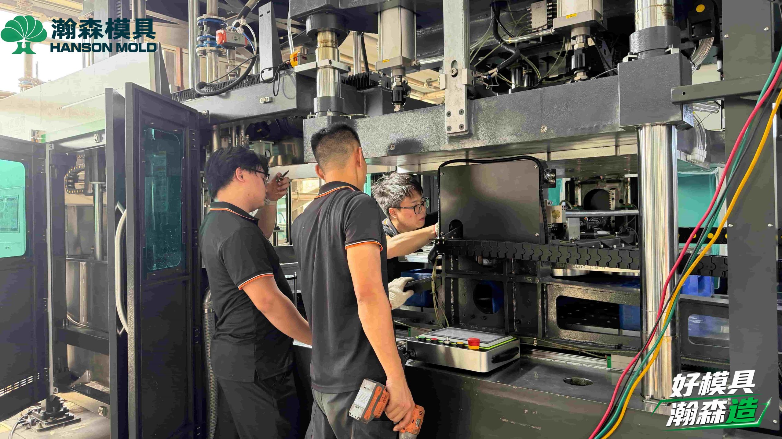
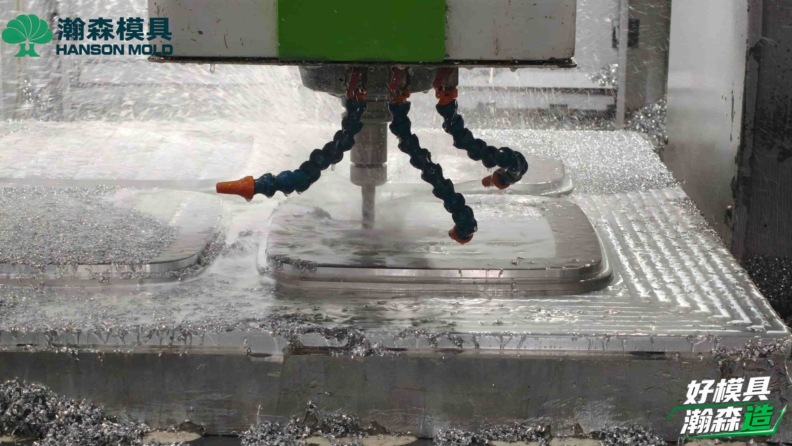
The consistency of a multi-cavity tool is fundamentally rooted in machining precision. With over 500 pulp molding molds manufactured to date, Hanson Pulp Molding leverages extensive experience to control multi-cavity variables. During the manufacturing process, we utilize high-speed CNC machining centers (reaching up to 24,000 RPM) to ensure the geometric dimensions of every cavity remain strictly identical.
Before the wire mesh is applied (the covering process), our quality control team uses 3D scanning equipment to capture point cloud data of each machined cavity. This data is overlaid and compared against the original 3D CAD model. Only when the geometric tolerances of the entire platen meet our strict criteria does the tool proceed to the drilling and meshing stages, preventing “congenital” dimensional defects at the source.
Troubleshooting Priority: Tooling, Pulp, or Machine?
When providing mass production support or optimizing old molds, poor consistency shouldn’t automatically be blamed on the tooling. On-site troubleshooting must follow this priority sequence:
-
Pulp and Process Conditions: Verify that the pulp concentration in the vat is uniform (no stratification) and that the vacuum levels are stable and adequate.
-
Machine Platen Parallelism: Check the alignment and parallelism of the upper and lower platens on the thermoforming machine. Uneven mechanical pressure will lead to insufficient pressing on the edges, causing excessive thickness.
-
Tooling Hardware: Once process and machine variables are ruled out, use the product cavity marks to pinpoint the exact mold sections. Unbolt those specific cavities to check for damaged mesh, resin build-up on the backing, or localized wear on the hot press mold. All diagnostic conclusions must be verified by on-site operational data.
-
FAQ
-
Q: Why are products in the center of the mold platen usually heavier than those on the edges? A: This is often related to vacuum distribution and pulp fluid dynamics. When the forming mold dips into the slurry, vacuum suction is sometimes more concentrated in the center manifold. Additionally, edge cavities might have marginally less immersion time depending on the machine’s entry angle. Optimizing the tooling’s internal vacuum channels can mitigate this.
-
Q: If a specific cavity is overweight, can we modify the tool directly? A: If verified as a cavity volume issue, an overweight cavity can be carefully adjusted via CNC machining to reduce pulp intake volume. However, if it is underweight, expanding the cavity or altering the drainage hole distribution to increase suction requires careful evaluation based on 3D scan data before making any irreversible cuts.
-
Q: During tooling acceptance, dimensions are fine but demolding is difficult. What went wrong? A: Demolding issues can stem from insufficient draft angles, inadequate surface polishing, or incorrect hot press temperatures. If tool path marks from rough CNC machining weren’t polished out, or if the wire mesh isn’t fitting snugly, sticking risks increase. On-site observation during the trial run is essential for diagnosis.
-
-
Experiencing consistency issues during your multi-cavity tooling trials? Contact Hanson Pulp Molding for expert tooling evaluation and on-site mass production support to ensure your project delivers uniform, high-quality molded fiber products.