
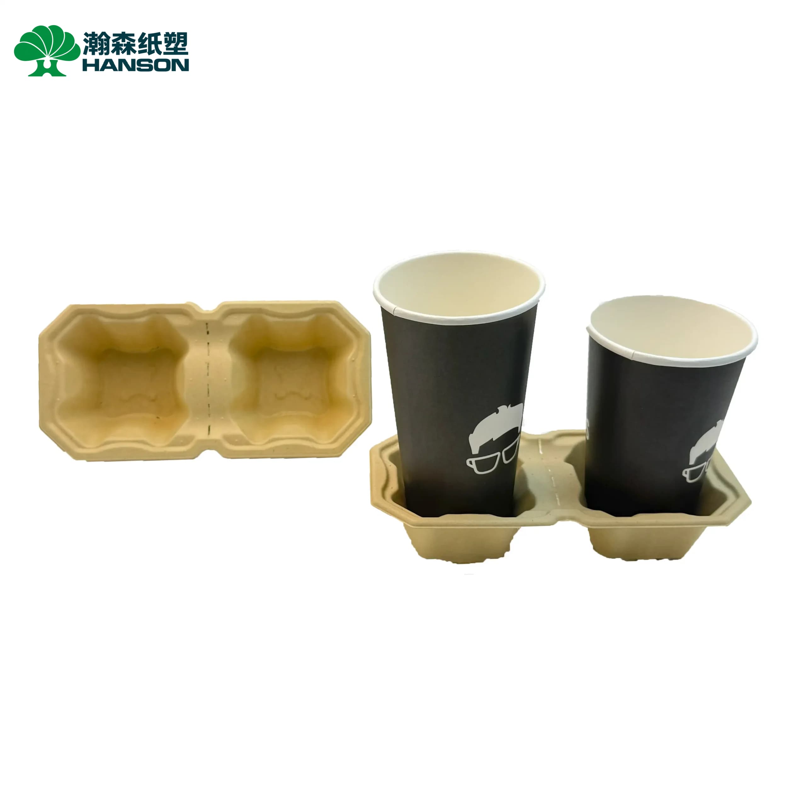
For molded fiber coffee cup carriers, a successful tooling design must balance two critical factors: secure load-bearing capability for beverage transport and high nesting density to minimize shipping costs. As a high-volume food packaging product, cup carriers must accommodate various cup sizes (e.g., 8oz, 12oz) while utilizing precise draft angles and reinforcing ribs to ensure the carrier doesn’t snap under weight, even in humid conditions.
Key Structural Variables in Cup Carrier Tooling Design
Coffee cup carriers are typically produced using the dry-press process (utilizing recycled OCC or ONP pulp) or semi-dry processes. Since they do not require the ultra-smooth surface finish of high-end electronics packaging, tooling design should heavily prioritize structural mechanics and release efficiency.
1. Cup Fit and Anti-Slip Retention
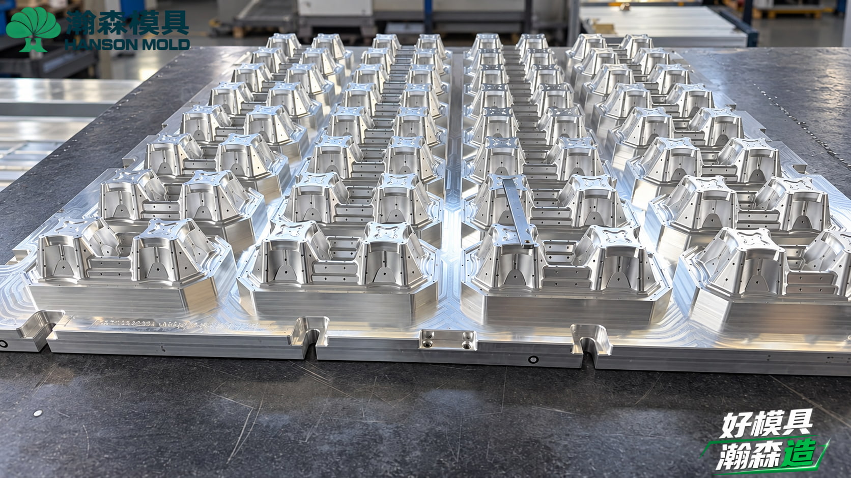
The cavity of the cup holder must taper downwards to securely grip the lower half of the paper cup. During the 3D mold design phase, engineers must import standard cup 3D models for interference checking. To increase friction, 3 to 4 tiny retention nubs (grippers) are often designed into the cavity walls. Machining these small features requires extremely fine CNC tooling. Furthermore, during the wire mesh covering process, the mesh must fit these nubs tightly; otherwise, pulp buildup or tearing may occur during forming.
2. Nesting Efficiency and Draft Angles
In the food packaging industry, logistics costs are paramount. The nesting pitch of cup carriers determines how many units can be packed into a master carton.
-
Setting Draft Angles: To achieve tight nesting and ensure smooth ejection from the mold, the draft angle on the outer walls of the cup carrier tooling is generally set between 5° and 8°. If the angle is too small, the product may tear during ejection or jam tightly together (locking) when stacked. If the angle is too large, the product footprint expands, reducing carton utilization.
-
Nesting Lugs/Steps: Tooling engineers must incorporate nesting lugs (small steps or stand-offs) at the bottom or sides of the cavities. These provide a resting point when products are stacked, preventing them from telescoping and locking together, allowing baristas to easily pull a single carrier with one hand.
3. Load-Bearing Structural Ribs
When a barista lifts a fully loaded 2-cup or 4-cup carrier, the central bridge area bears significant bending moments. Tooling designers must layout “X” or cross-shaped structural ribs in the connecting areas between cup cavities. On the forming mold, these ribs appear as deep grooves. The drilling of vacuum holes must be densely concentrated in these corners and deep recesses to ensure adequate pulp deposition, achieving the necessary thickness and strength.
Pre-Molding Checklist for Molded Fiber Cup Carriers
Before finalizing 2D/3D tooling drawings, confirm the following core parameters to avoid costly tooling modifications later:
-
Pulp Type and Shrinkage Estimation: Confirm whether the material is recycled corrugated carton (OCC), newsprint (ONP), or virgin bagasse. Shrinkage rates vary significantly depending on the fiber (typically between 3% and 8%). The mold design must compensate for the specific shrinkage rate of the chosen pulp.
-
Machine Compatibility: Identify if the mold will be mounted on a rotary, reciprocating, or flip-type forming machine. The mounting hole locations, vacuum chamber layout, and backing plate design vary entirely based on the equipment.
-
Load Requirements: Determine the maximum liquid weight the carrier must hold (e.g., four large iced coffees, approx. 2.5kg) to reverse-engineer the required wall thickness and wire mesh gap in the mold.
From Mold Trial to Mass Production: Hanson Pulp Molding’s Expertise
While cup carrier molds seem simple, the machining precision of deep cavities directly impacts yield rates. With an independent tooling department and 500 pulp molding molds manufactured to date, Hanson Pulp Molding ensures delivery quality through critical manufacturing nodes:
-
High-Speed CNC Machining: Utilizing CNC centers with spindle speeds up to 24,000 RPM, we ensure smooth cutting surfaces on deep cavities and ribs, significantly reducing manual polishing time.
-
3D Scanning Inspection: After fine machining, 3D scanning is employed to compare physical molds with theoretical CAD data, ensuring draft angles and anti-slip nubs are strictly within tolerance.
-
Mold Trial and Production Support: For clients utilizing a “New Mold + Non-Hanson Equipment” pathway, we assemble and test the complete tooling set in-house before delivery. We then provide comprehensive mass production support, advising your on-site engineers on installation and vacuum/air pressure adjustments to perfectly match your actual production line.
Troubleshooting Common Mold Trial Issues
When testing a new cup carrier mold on the machine, address the following issues by priority:
-
Thin Walls or Holes at the Bottom/Sides
-
Tooling Check: Inspect if the vacuum holes on the forming mold are blocked by pulp residue. Check for damaged wire mesh or overlapping wires that restrict water drainage.
-
Process Check: Verify if the pulp concentration is too low or if the vacuum suction time is too short.
-
-
Difficult Ejection or Sidewall Tearing
-
Tooling Check: Re-verify the draft angle of the torn area using an angle gauge. Ensure the blow-off air holes on the transfer mold are evenly distributed. Deep-cavity products like cup carriers often require a sudden, high-volume burst of air from the transfer mold for clean ejection.
-
Machine Check: Ensure the mechanical transfer action of the forming machine is perfectly aligned, without micro-lateral shifts causing friction.
-
-
FAQs
-
Do coffee cup carriers require hot pressing molds? Answer: It depends on the target market. Standard recycled OCC carriers (used for quick takeout) use a dry-press process, moving directly into drying ovens without hot pressing, resulting in a rougher texture. High-end bagasse carriers requiring a smooth finish and embossed logos will require secondary hot pressing (thermoforming) molds.
-
Why do the cup carriers stick together in stacks after production? Answer: This is a classic nesting design flaw. It is caused by insufficient draft angles or the absence of “nesting lugs” in the mold design. The solution requires modifying the mold to add small stand-offs (lugs) on the side walls or base to maintain a fixed stacking gap without compromising strength.
-
If the carrier snaps during load testing, must the entire mold be scrapped? Answer: Not necessarily. First, optimize the pulp formulation (e.g., adding longer fibers) and forming time to increase thickness. If the issue is purely structural, the tooling can often be locally modified by deepening the structural ribs at the failure point (usually the central bridge), avoiding the need to scrap the entire mold set.
-
-
Are you experiencing ejection difficulties or poor nesting efficiency during your pulp molding product development? Hanson Pulp Molding provides end-to-end solutions, from 3D structural optimization to complete mold manufacturing. Contact us at [+86 15920604830] or reach out to our engineering team for tooling evaluation and production support.