
How to Evaluate Molded Fiber Tooling Samples: Beyond the “Golden Sample”
Accepting a molded fiber tooling sample requires far more than approving a single, visually flawless prototype. A true mold quality inspection must evaluate the tooling under simulated mass-production conditions, utilizing standardized process parameters. The focus should be on verifying multi-cavity consistency, demolding reliability during continuous cycles, and precise dimensional data derived from 3D scanning. Only tooling that passes these rigorous tryout criteria can guarantee smooth project delivery and stable mass production.
The Trap of the “Golden Sample” in Pulp Molding
During the mold trial (tryout) phase, suppliers often present a few perfectly formed sample pieces. These “golden samples” are frequently hand-picked and produced under unusually long cycle times that allow for perfect water drainage and fiber formation. They do not accurately represent how the mold will perform under the relentless pace of an actual production run.
If you base your tooling acceptance solely on the weight and aesthetics of a single piece, you risk facing severe issues during mass production. These problems can include significant weight variations across different cavities, excessive flash on product edges, and frequent machine downtime caused by products sticking to the mold. Therefore, your evaluation must shift from inspecting individual parts to analyzing the dynamic, continuous operation of the tooling itself.
Core Metric 1: Multi-Cavity Consistency
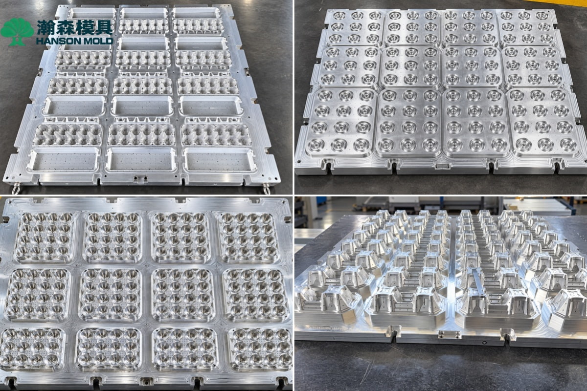
For multi-cavity molded pulp tooling—commonly used for tableware, cup lids, or molded fiber inner packaging—consistency is the ultimate indicator of machining precision. Poor runner design or insufficient CNC machining accuracy will lead to uneven pulp slurry distribution among the cavities. This results in noticeable variations in weight, wall thickness, and overall dimensions across the same batch of products.
During the acceptance phase, randomly select products from at least five consecutive shots. Measure the wall thickness and dry weight of products from both the center and edge cavities. A qualified mold will maintain a highly restricted tolerance range across all cavities. Hanson Pulp Molding utilizes high-speed CNC machining centers (operating up to 24,000 RPM) during the fine machining phase, followed by strict stress relief and 3D scanning. This workflow inherently guarantees the physical precision of the multi-cavity array, ensuring every cavity performs identically.
Core Metric 2: Demolding Efficiency and Repeatability
Demolding is often the most critical bottleneck in the pulp molding process. During tooling acceptance, you must observe how the mold performs during continuous operation (e.g., observing 50 or more consecutive forming and transfer cycles). If sticking or product deformation occurs, do not immediately blame the tooling. You should troubleshoot based on the following priorities:
-
The Tooling: Check if the draft angles are sufficient, ensure the wire mesh (for wet-press processes) is tightly fitted without dead angles, and verify the uniformity of the surface polish or Teflon coating.
-
Pulp Formulation: Confirm whether the pulp freeness is appropriate for the product and if water/oil sizing agents are correctly dosed.
-
Equipment Parameters: Ensure the vacuum suction reaches the set values, the alignment between the forming mold and transfer mold is precise, and the compressed air blow-off timing is synchronized correctly.
A mold proves its repeatability and readiness for project delivery only when it can sustain high demolding yields during continuous trials.
Core Metric 3: Data-Driven Mold Quality Inspection
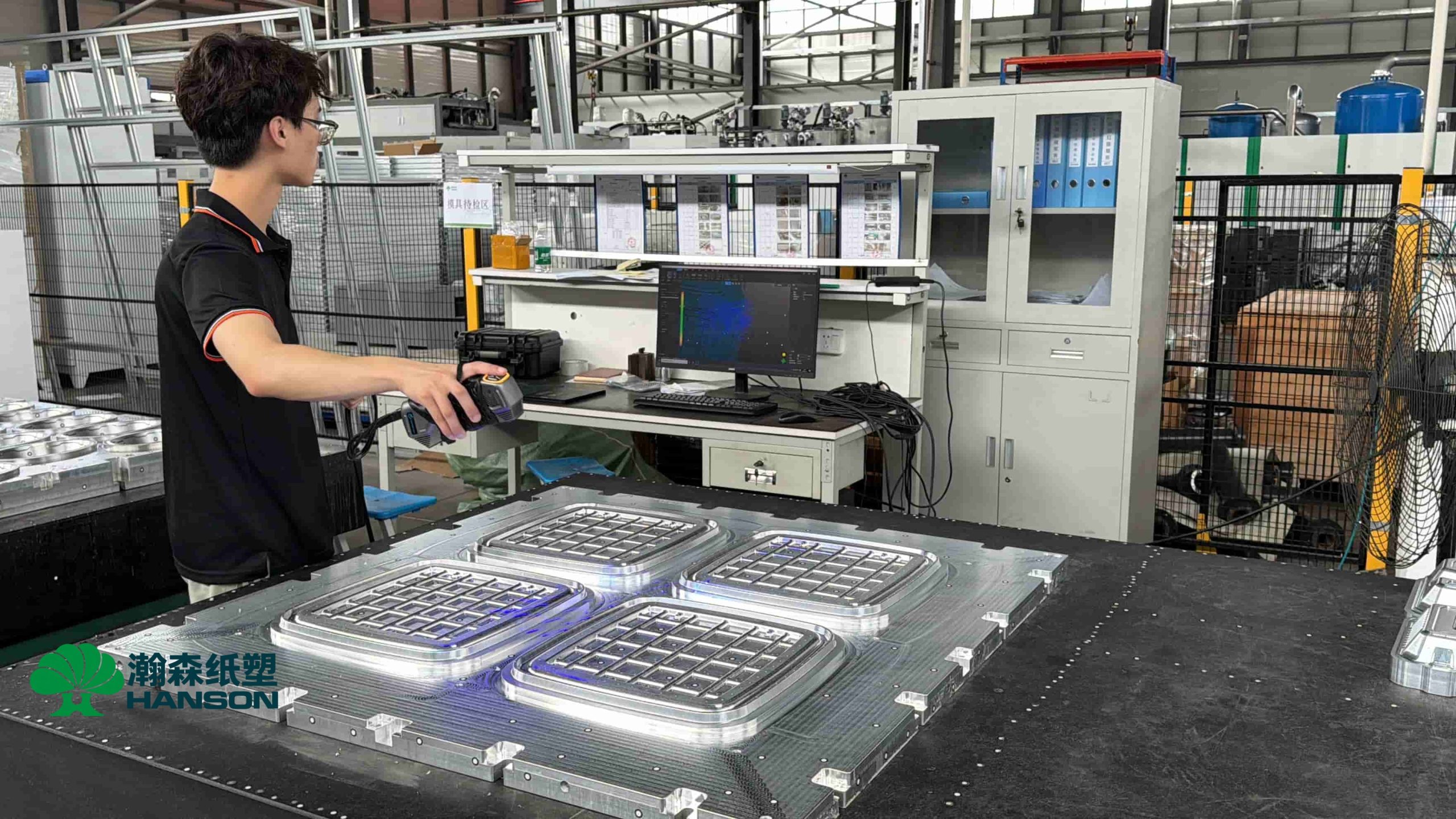
Never accept a mold based purely on visual or tactile impressions. The final defense in project delivery is empirical data. Sample parts must undergo rigorous dimensional and geometric tolerance checks. Use a thickness gauge to measure critical stress points and employ 3D scanning technology to compare the physical sample directly against the original CAD file, generating a color-coded deviation map.
Furthermore, verify that the actual cycle time achieved during the tryout meets the initial design specifications. Hanson Pulp Molding provides comprehensive 3D scanning reports and detailed tryout data sheets after the drilling and assembly stages, ensuring that every mold delivered is fully documented and verified.
Seamless Project Delivery and Mass Production Support
A superior molded fiber mold is not just a block of metal; it is a complete production solution. Whether integrating a new mold with Hanson equipment or running it on non-Hanson machinery, comprehensive tooling services must cover everything from product development to mass production support. With 500 pulp molding molds manufactured to date, Hanson Pulp Molding understands both tooling design and on-site process engineering. We provide on-site tuning services to help troubleshoot yield issues caused by pulp properties, operational sequences, or mold interference, turning your approved samples into profitable mass-produced goods.
Planning to develop a new molded fiber product or looking to optimize an existing mold? Contact Hanson Pulp Molding for comprehensive tooling solutions, from sample evaluation to on-site mass production support.
-
FAQ:
-
Why do samples look perfect during tryouts, but sticking occurs during mass production? Tryouts often run at slower speeds with perfectly clean molds. Sticking during mass production can result from slight mold deformation due to continuous heat, wear on the surface coating, or the vacuum/temperature parameters failing to keep up with high-speed cycles. Continuous fatigue testing during acceptance is essential.
-
What are the most important measurements when inspecting multi-cavity molds? Focus on the dry weight differences between the center and edge cavities, the wall thickness at critical snap-fit locations, and the overall draft angles. Comparing the physical sample to the original CAD file using a 3D scanner is the best way to detect multi-cavity consistency errors.
-
Is flash or burr always caused by poor mold machining precision? Not necessarily. While inadequate CNC fine machining can cause flash, uneven wire mesh fitting, excessive clearance between forming and transfer molds, or overly high pulp consistency can also lead to burrs. This requires on-site troubleshooting adjusting process parameters alongside mold checks.
-